

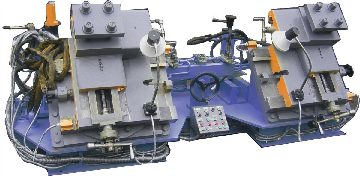
VTU-01 Underfloor wheel lathe
VTU-01 wheel lathe used as a technological equipment in the locomotive or trams depot. It used for turning treatment of the railway wheel set rolling profile.
Main technical data:
| Parameters or dimensions | Unit | Value |
|---|---|---|
| Parameters of wheelpairs | ||
| Track gauge | mm | 1520* |
| Min. wheel diameter | mm | 900** |
| Max. wheel diameter | mm | 1250 |
| Max. wheel profile width | mm | 150 |
| Max/ wheelpair load | ton | 20 |
| Processing parameters | ||
| Max/ cutting depth | mm | 4 |
| Carriage feed (stepless regulation) | mm/min | 8...40 |
| Cutting speed (nominal) | m/min | 80*** |
| Hydraulic system parameters | ||
| Working pressure | MPa | 16 |
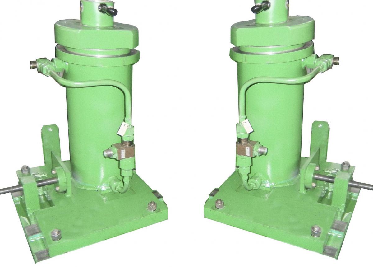
| Wheelpair lifting devices load capacity | ton | 2х25 |
| Traction motor support jacks load capacity | ton | 2х5 |
| Electrical system parameters | ||
| Main drive motor power | kW | 7,5 |
| Feed drives motors power | kW | 2х0,75 |
| Hydraulic station motor power | kW | 4 |
| Constructive power of machine | kW | 20**** |
| Electrical network parameters | - | 400V 50Hz |
| Overall dimensions and weight | ||
| Lenght (installed,without electric and hydraulic equipment) | mm | 5910***** |
| Width (installed) | mm | 2650 |
| Height (from the floor of the pit) | mm | 1560 |
| Pit depth (from the rail head) | mm | 1575 |
| Weight | kg |
5000***** |
* We have possibility of manufacture the lathe for another track width on customer`s request.
** Possible to make special option for another wheel diameters.
*** Main drive may be with step or stepless regulation of rotation speed.
**** Power for standart model
***** Parameters for standart model for track gauge 1520mm/
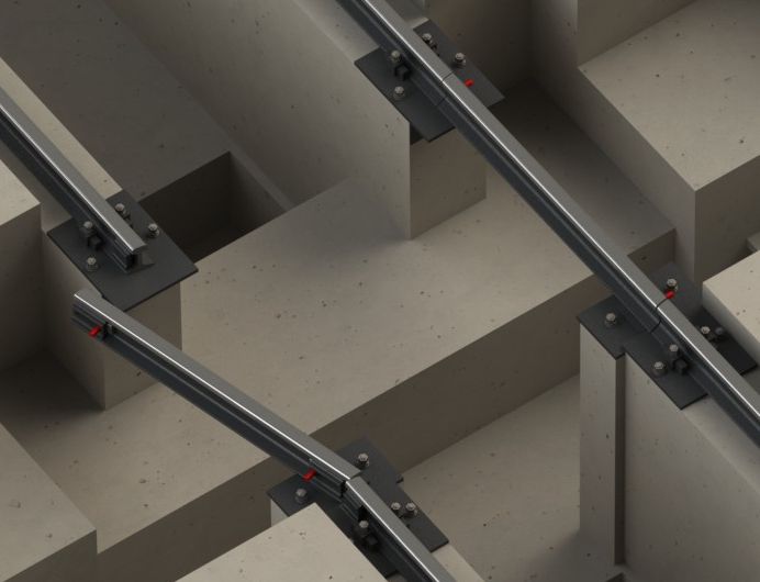
The lathe is installed on a foundation in the pit bellow the rails (underfloor).
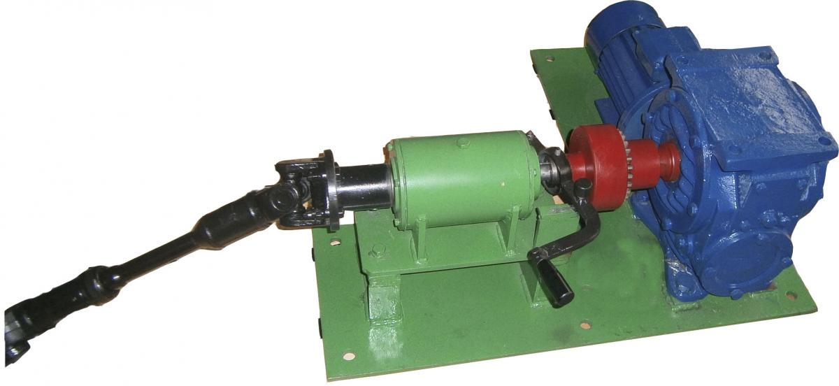
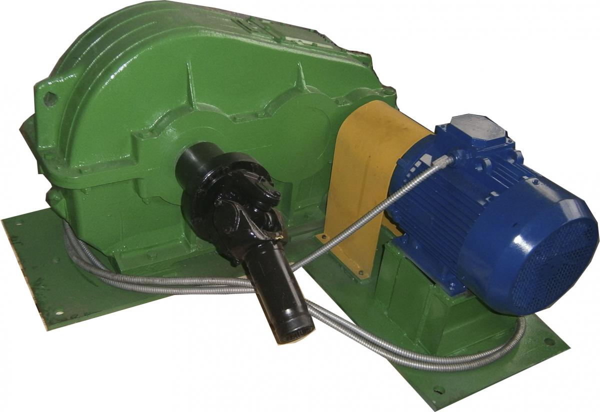
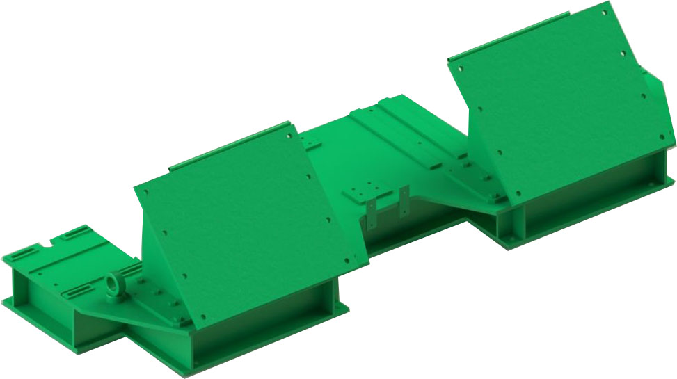
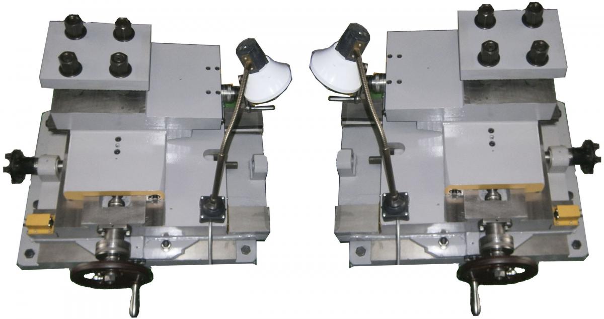
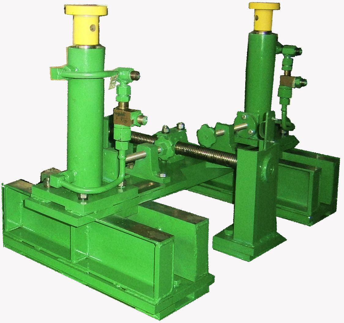
Main parts of the lathe:
|
|
|
|
|
|
|
|
|
 |
|
 |
|
 |
|
 |
|
 |
|
 |
|
 |
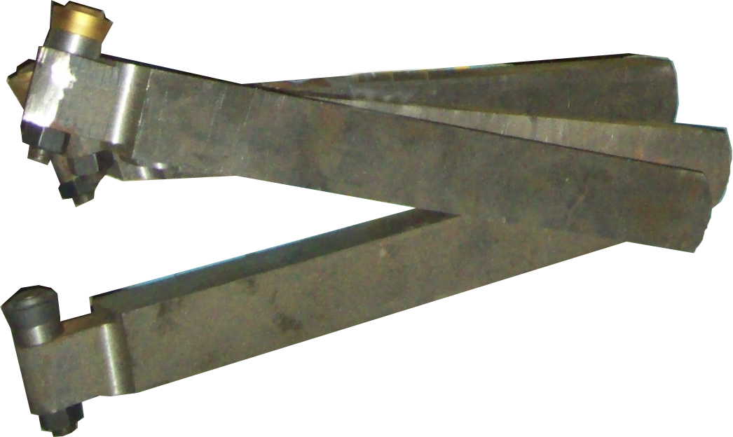
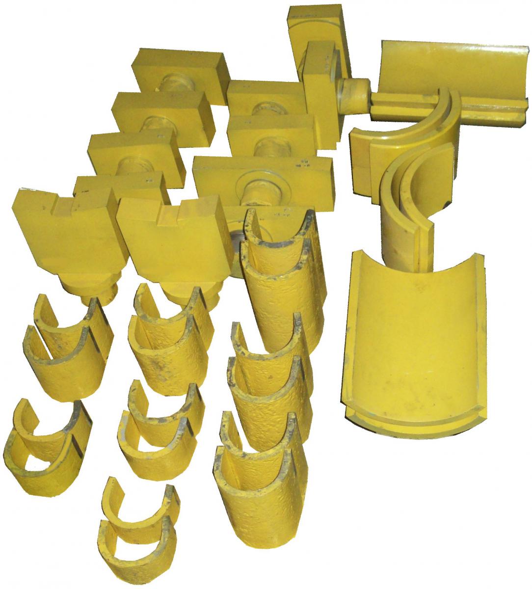
Changeble tools and equipment:
|
 |
|
 |
Differences from existing analogues
- Underframe design.
- Using of standart serial gears in drives;
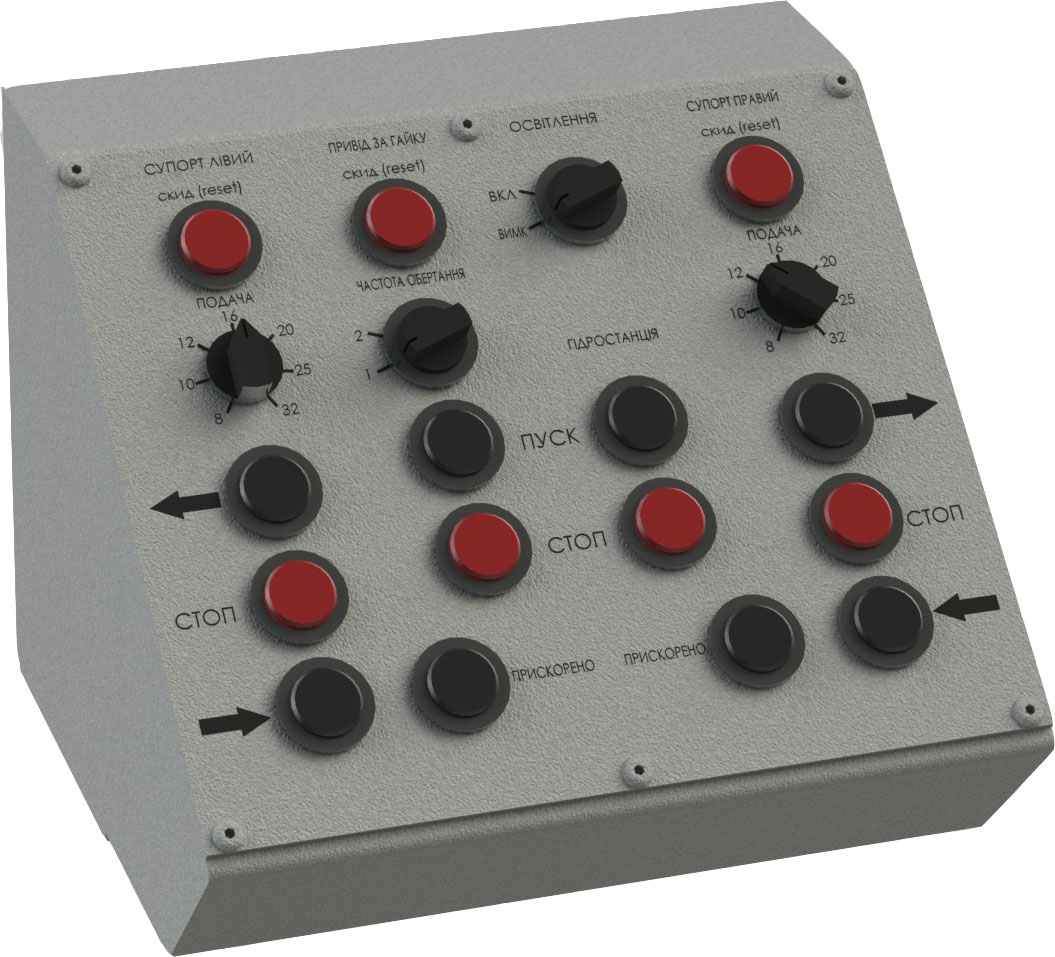
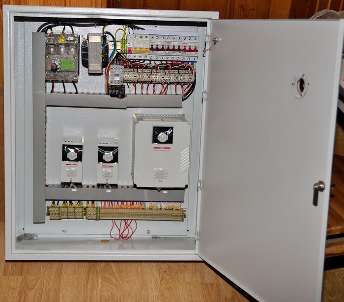
- Using of the frequency inverters for drive motors control. It provides stepless ajustment of the feed and main drive speed (optional). Also it provides smooth start and stop of drives.
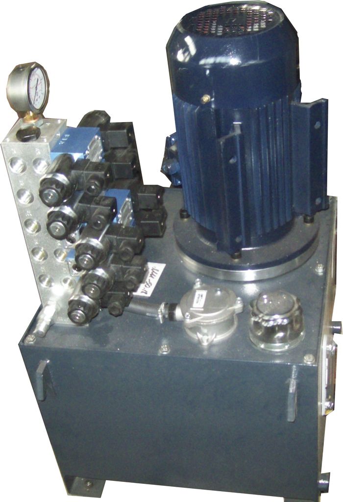
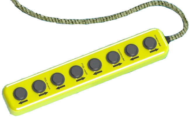
- Using of the hydraulic station with electric control. It provides controlling of the lifting devices and traction motor support device from the portable unit.
- Using of the standart cardan shafts in drives.